It’s time to answer some of your RVing questions. As you know, the channel focuses on helping those getting started with RVing and provides detailed do-it-yourself RV maintenance videos, RV news, and campsite reviews. So, let’s jump into the questions.
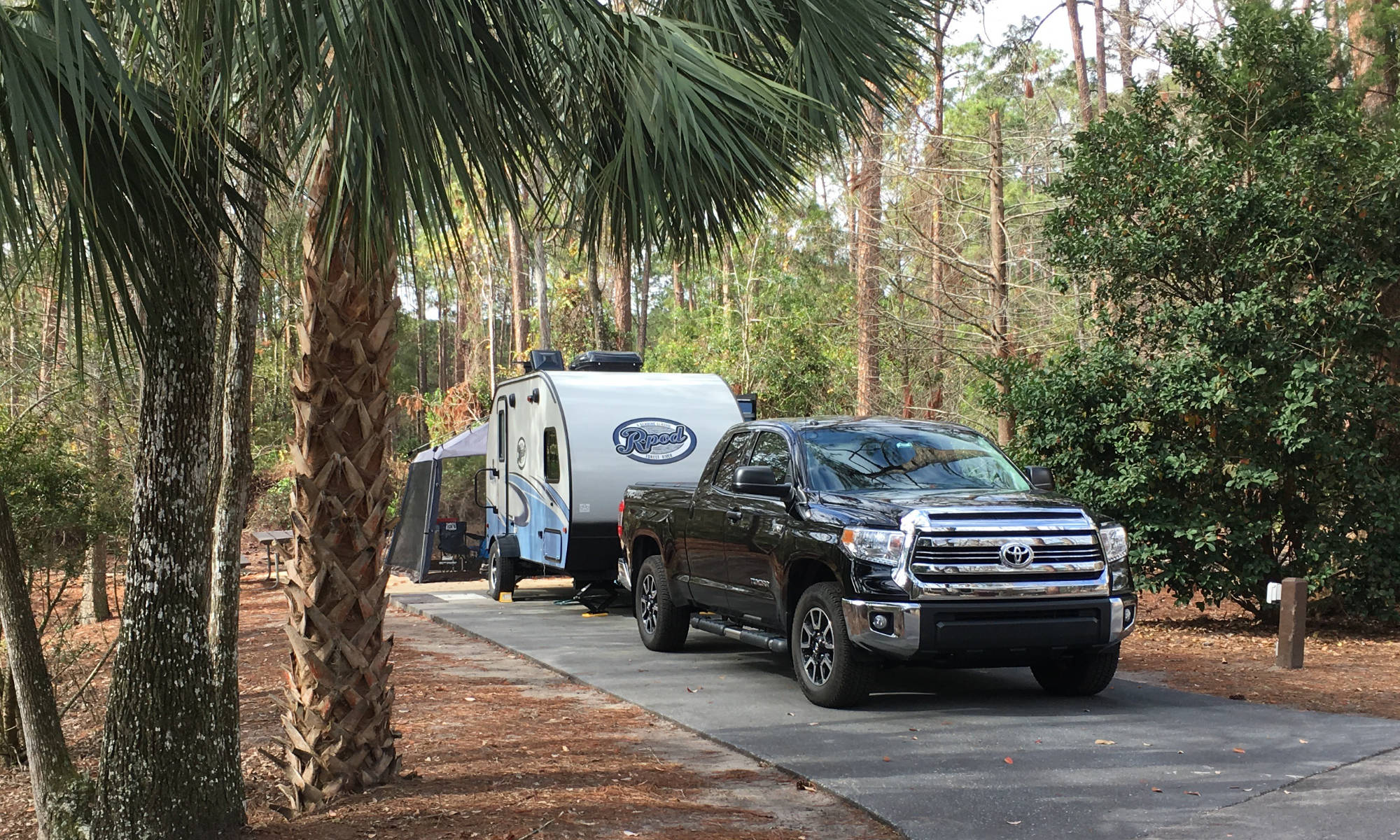
From our popular Backing Into a Campsite video monsterhml1574 shares a tip which leads to a great question:
I would like to share a personal tip that I always follow. Before backing into a site, I remove the weight distribution bars. This simple step provides more flexibility during the backup maneuver, reducing the stress on the components.
This begs the question: Should you remove weight distribution hitch bars before backing in?
John: First, I admit I never do this. I have always left my Blue Ox WDH connected, but it has a good deal of flexibility given its chain setup vs hard bars. I generally agree that removing the bars is a good idea on a WDH with them. The problem you may run into is where to do this when you get to the campsite. Pressure will need to be removed from the bars to release them, which usually means jacking up the front ball somewhere. So, you need to think ahead and stop somewhere (other than in front of the campsite, potentially blocking traffic) to jack the trailer up.
From the Dewinterization video, jonathanstrohl8589 asks:
Shouldn’t the first step be to flush all of the antifreeze out of the lines before switching off the bypass to the water heater? Otherwise, antifreeze will get into the water heater. No?
John: This is a good observation by Jonathan. A very minor amount will seep into the water heater, but it will immediately be diluted. I have dewinterized dozens of times and have never had an issue. You can feel free to flush the lines first before opening the bypass valve to the water heater. If you do it my way, a small amount will get into the tank; then it will be immediately diluted and flushed.
Ericsurprenant2110 asks:
I’m new to RV-ing. My question is, obviously all the water during this process is being drained into the black and grey tanks, so where do you empty those if you’re at home while doing the de-winterization?
John: This is a very common question. I usually do not de-winterize until I am about to go camping. I am not sure why you would. The amount of water and RV antifreeze going into the black and gray tanks is minimal. I simply dump the tanks when I dump after my first camping trip. So, I will dewinterize and flush into the holding tanks, then go camping and further dilute the holding tanks through normal camping use during that first trip, then dump at the end of the trip.
From the RV Dump Station Basics for Beginners video JasonBartels asks:
Can the black tank be filled with a few gallons of the non-potable water at the washout inlet? Any specific reason why doing it at the toilet aside from having to do the chemicals at the same time?
John: You can add the 4 gallons or so to the black tank via the black tank flush inlet vs. the toilet, as shown in the video, but without having a water meter on the inlet, you can’t tell how much you are putting into the tanks. Also, I would never use this water meter for anything else after this, given how dump station non-potable water hoses are used.
Also, water weighs over 8 lbs. per gallon, so leaving too much water in the tanks adds unnecessary towing weight and, depending on the tank’s placement, could introduce a sway issue while towing. To me, it is safer to add water via the toilet after the process is complete.
On the High Pointe Convection Microwave Oven video, mknbkn4u2 asks:
When you use a combo function…what about the fact that you shouldn’t have metal in the oven for the microwave portion but then need to use the metal rack to raise the dish to allow proper air circulation for even cooking?
John: The round metal rack that comes with the unit has rubber feet and is safe to leave in when transitioning to/from using the microwave in combo mode. Just don’t let the rack touch the sides when it is rotating. This is a common question, but the unit is made for transitioning between modes.
On our RV Water Pump Troubleshooting video, Fdxman asks:
Hey John, my freshwater tank is full, when I turn on the water pump, water is coming out of the city water connection? Any Ideas?
John: It sounds like your check valve may be stuck open, allowing water to flow back to the city water line. The pump may be clogged with debris. You may want to disassemble it like shown in the video and clean any debris out.
This can be an issue, particularly with new RVs. Most RVs come with a large plastic freshwater tank that has been drilled for various inlets and outlets. Of course, when this is done, the plastic shavings end up in the tank. When the first owner uses the fresh water tank, these shavings end up stuck in the water pump, causing the check valve to stay open and allowing water to flow back to the tank or, in some cases, out of the city water inlet. It isn’t difficult to fix and is something to be aware of when buying a new RV.
Other Questions
What is the craziest thing you’ve seen at a campsite?
John: I was returning from northern Michigan, and the campground we left didn’t have a working dump station, so we drove down to a state park near Cadillac, Michigan, to dump. It worked well, and as I was dumping, a guy and his boy came up with a portable dump tank and poured out their waste at the opposite dump station without any hose or connection. Just lift and pour, trying to get the contents into the round hole! Not much made it on the first try. It was one of those moments when you see something but don’t believe what you are seeing. Fortunately (or unfortunately) I was dumbfounded and didn’t reach for the camera.
What is the thing that annoys you most when camping?
John: Not even close, it’s other people’s music played for everyone to hear. I like music, but for whatever reason, it is a mind virus to me, and I have a real issue with music sticking with me. I understand that people camp to kick back, but at most campgrounds, you are near other people, and the inconsideration bothers me.
Is there any brand of RV you wouldn’t buy again?
John: See all of my travel trailer videos! I honestly would not buy any RV I’ve owned or currently own. They’ve made for great channel video content to help people with issues, but I can’t recommend any of them, nor would I buy them again. It makes for a real dilemma when even thinking about replacing what I have.
Someone asked: were you a teacher in a past career?
John: I consider myself a teacher by nature, and although I taught some classes at the college level, I never taught as a profession. I did have a programming, data, and financial analytics career that ties nicely to the channel. This is why our newscasts are data-oriented and our DIY videos are very methodical. Overall, I seem to be teaching all the time in one facet or another, and for some reason, I am able to take complicated issues and reduce them to understandable concepts to help people.
Ok, that will do it for this Q&A. All the best!